Consider the following junction:
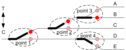
Exit route B is accessible because point 1 & 2 are THROWN while point 3 is CLOSED. The LEDs on that path are lit. All of the LEDs for point 4 are off, because you can't reach that point because of the setting on point 1.
To program this logic in the DTM30 is simple. Lets assume that points 1-4 are assigned to cells 5, 7, 9 & 22 respectively.
| Point | Cell | Cascade programming |
| 1 | 5 | none |
| 2 | 7 | cascade from cell 5 THROWN |
| 3 | 9 | cascade from cell 7 THROWN |
| 4 | 22 | cascade from cell 5 CLOSED |